


Amo® III 7.5 type 2 window frame screw Cylinder head 8.0 mm
Amo III type 2 steel zinc-plated RW 30
SCR-RW30-(A2K)-7,5X92
AMO III


Register now and access more than 10,000 products
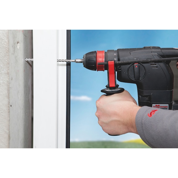
- Short installation times, no setting tool or anchor required
- RW recess for longer bit service life and improved power transmission
- In-place installation
- Mechanical interlock for high load capacity
- Virtually no expansion forces during installation
- Window installation possible without side supporting blocks and spacer blocks (depending on the installation conditions, confirm using the ift installation tool)
- Removable anchorage with mechanical interlock and no expansion pressure
- Load-bearing capacity is retained even under thermal stress
- Tested fire resistance period of 120 minutes
Fire protection test report no. 3174/0649-2 dated 12 January 2000 in concrete
Test of suitability for attaching a flood-proof window in accordance with ift directive FE-07/1 conducted by the ift Rosenheim Institute.
Test report no. 202 31790 dated 17 May 2006
Component test with frame screws to attach a glazed plastic door (window casement weight 72.5 kg) to a structure without lateral supports or sand-lime brick masonry.
Tests carried out without lateral support and spacer blocks, ift Rosenheim: Test report 105 34261 dated 21 November 2007
Component test with frame screws to attach a glazed plastic door (window casement weight 70 kg) to a structure without lateral supports or sand-lime brick masonry.
Testing carried out without any lateral supports or spacer blocks.
ift Rosenheim: Test report 105 35697 dated 31 March 2008
Component test with frame screws to attach a glazed plastic door (window casement weight 70 kg, screw connection in profile without steel reinforcement) to a structure without lateral supports or sand-lime brick masonry.
Testing carried out without any lateral supports or spacer blocks.
ift Rosenheim: Test report 105 43036 dated 21 October 2010
Datasheets(X)
CAD data (available after login)

- Tension-free stand-off installation for wooden, plastic and aluminium window frames
- Frame coupling
- Mounting of window installation brackets, window shackles, swivel anchors and knock-in claws (short version of Type 3)
Guidelines for planning and executing the installation of windows and house doors, 2020 edition
Art. no. 5995000000:
The fixture must safely transfer all standard forces affecting the window to the structure and the foundation. The total load must therefore be calculated from e.g. the window load, wind load and live load (see DIN 1055). The currently applicable building regulations stipulate that buildings and their components must be planned in such a way that they do not endanger human life and health or pose a risk to public safety. Attachment of the windows must also comply with this criterion.
When securing window walls compliant with the former DIN 18056 standard or elements with a surface area in excess of 9 m2 and fall-proof glazing as specified in the German technical rules for safety glazing (TRAV) or DIN 18008-4, the following must be observed
The DIN 18056 standard applied to window walls with a minimum surface area of 9 m² and a minimum side length of 2 m on the shortest side. Anchors with construction product approval, European technical approval or with individual approval should be used for this application. Similarly, only anchors with construction product approval, European technical approval or with individual approval must be used to attach fall-proof glazing as specified in the German technical rules for safety glazing (TRAV) or DIN 18008-4.
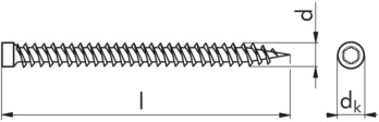 | |
Length (l) | 92 mm |
Thread diameter (d) | 7.5 mm |
Material | Steel |
Surface | Zinc plated |
Head type | Socket head |
Head diameter (d(h/k)) | 8.0 mm |
Internal drive | RW30 |
Thread type | Dowel screw thread |
Shape of tip | Tip |
Performance data | |||||
Anchor type | Type 1 | Type 2 | Type 3 | ||
Fire resistance rating Concrete compressive strength at least C20/25 and at most C50/60 | Centric tension load | F30 [kN] | 0,80 | - | 0,80 |
F60 [kN] | 0,55 | - | 0,55 | ||
F90 [kN] | 0,45 | - | 0,45 | ||
F120 [kN] | 0,40 | - | 0,40 | ||
Transverse or diagonal tensile force up to 30° | F30 [kN] | 0,50 | 0,50 | 0,50 | |
F60 [kN] | 0,50 | 0,50 | 0,50 | ||
F90 [kN] | 0,50 | 0,50 | 0,50 | ||
F120 [kN] | 0,50 | 0,50 | 0,50 | ||
Last viewed

Air-conditioning leak stop Plus

Low-profile nylon insert lock nut (non-metal insert) inch Similar to DIN 985, steel GR5, zinc-plated, blue passivated (A2K)

1/2" connection

Expanding nut, type 6 Suitable for long holes

Heat-shrink crimp ring connector

Pozidriv screwdriver (PZ) with hexagon shank

Ratchet multi-bit screwdriver with pistol handle Set of 37 pieces

Sealing ring, copper, shape A

Twist drill bit HSCo DIN 338 type RN bronze point thinning

1/4" socket wrench insert metric, long